


About 3D analysis tools
The 3D analysis tools provided for managing the drilling process are following:
-
The Critical distance tool is provided to find any intersection of wellbores of one well and to calculate critical distance between these wellbores;
-
The Distance from target-point to bottomhole tool is provided for calculating the distance between the selected target-point and the bottomhole;
-
The Distance from node to wellbore tool is provided for calculating the distance between the selected node and the wellbore;
-
The Distance between nodes tool is provided for calculating the distance between selected nodes of two wellbores;
-
The Coordinates of wellbore geometry nodes tool is provided for viewing nodes coordinates of wellbore paths;
-
The Coordinates of nearest node tool is provided for specifying the coordinates of the nearest node with the mouse click;
-
The Boundaries intersection tool aimed to define the coordinates of the intersection points of wellbore geometry and license area.
- The Paths divergence tool is provided for calculating distance between adjacent wellbore paths.
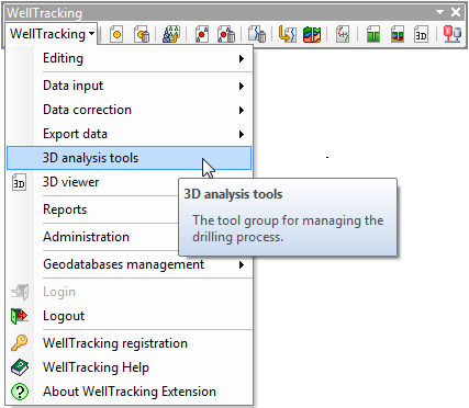
To start working with the tools select 3D analysis tools from the drop-down list of the WellTracking main menu.
3D analysis tools dialog
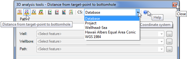
The name of the active 3D tool is shown in the dialog header.
The required tool can be selected from the toolbar provided in the upper left part of the dialog. The appropriate tool-tip with the name of the tool is shown when hovering the cursor over the tool icon
The CS (Coordinate System) text-box is provided to specify the coordinate system, which units will be used to display the resulting values. The X, Y coordinates are specified based on the mathematical model: X-Longitude East, Y-Latitude North. Z coordinate corresponds to the absolute depth value.
There are following coordinates systems in the list:
-
Database coordinate system - the projection units will be the units of your database.
-
Project coordinate system - the project units will be the units of your project. These units can differ from ones of the database projection.
-
Wellhead-Sea coordinate system - in this case the origin of coordinates is the wellhead.
The list of the standard coordinate systems (Database, Project, and Wellhead-Sea) can be extended with the custom coordinate systems using the Coordinate systems administration tool.
At the same time WellTracking system allows to manage the coordinate systems access permissions using the Groups administration tool. After the system administrator has specified the appropriate access permissions, the user will be able to work with those coordinate systems only, to which he has been authorized to have access.
*****