


Custom layer symbology
Specifying the map layout and features symbology settings is done while managing the layers list in ArcMap. This should be done before publishing the map service that will be included to your interactive map. ArcGIS provides the user with the option to change the layers order and symbology during single editing sessions.
If the symbology editing option is specified in your service, then the
Layer color setting button  will be enabled in the layer context menu of the interactive
map. The symbology editing option is provided to analyze data or to create
specific user maps that can be printed.
will be enabled in the layer context menu of the interactive
map. The symbology editing option is provided to analyze data or to create
specific user maps that can be printed.
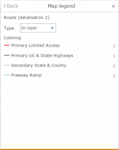
The Custom layer symbology tool allows editing the map layer features appearance. There are two options of the layer symbology provided for all types of layer features:
-
Single – unified symbol for all features
-
Range – symbology depends on the feature class. The feature class is defined based on the selected attribute and specified range values for this feature class. To specify the range color settings, select the attribute by which you want to color your layer in the Field line, and specify the number of ranges.
-
Unique – unique symbol defined for each unique value of the layer attribute. To set layer symbology by unique values, select the attribute by which the symbology will be created in the Field line.
Change the basic symbol by setting the required properties. For simple
rendering the basic symbol will be used to display all objects of the
layer, whereas for other types of rendering it will be used to define
symbol shape. To go to setting basic symbol properties, press Menu
button  .
Select symbol template and make required changes in the Change
symbol menu. Note that for
layers with different object types the symbol setting interface will be
different.
.
Select symbol template and make required changes in the Change
symbol menu. Note that for
layers with different object types the symbol setting interface will be
different.
Select the template from the list or create your own symbol. For layers containing different types of objects the symbology settings interfaces will differ.
|
For Point symbol type select the shape of the point, its fill and outline color, symbol size, outline width, and opacity. |
For Polyline symbol select the polyline type, color, width, and opacity. |
For Polygon symbol select the fill and outline color, fill type, outline width, and opacity. |
|
|
|
|
After you finish setting basic symbol, go to layer rendering menu and press Back button.
For rendering types Simple and Unique specify the initial and final colors, that will be used for setting gradient for symbols colors. You can set symbol properties for each feature class separately in case of rendering by range or unique values. This option is also enabled, if the complex symbology for layer has been specified.
Symbology templates - the new symbol can be saved as your own template. To save the template, enter its name and press Save button. The template will be saved in the My templates list of the Custom rendering dialog and will be further available when editing the layers rendering parameters in the Graphics drawing tool. Besides this, the templates can be saved as Map templates in the Saved drawing and layers rendering templates section of the User interface constructor tab.