


Step 2. Create license area geometry
At this step you need to select the method of creating license area geometry.
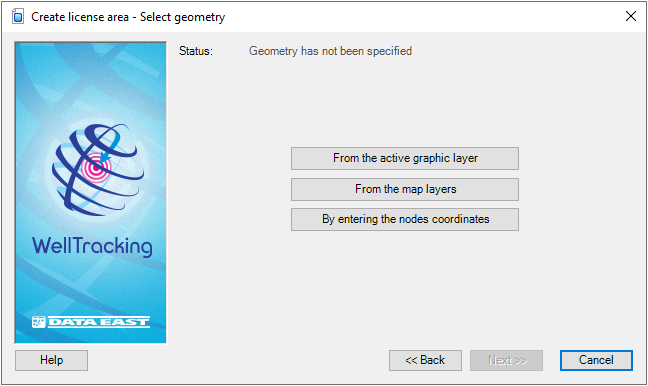
WellTracking extension provides three methods of setting geometry for the license area:
-
From the active graphic layer;
-
From the map layers;
-
By entering the nodes coordinates.
To create geometry in the graphic layer press From
the active graphic layer button. Select the required feature on
the ArcMap map (when getting inside the map area the cursor should look
like the cross hair  ).
).
The user can specify geometry of the feature to be created not only from the WellTracking database layers. The wizard can read data of other formats: shape-files and feature classes of other databases, in case if their projection coincide with the WellTracking database projection.
Press From the map layers button
if the geometry of your license area is in one of the map polygon layers.
Then point the cursor
to the required feature. You can change the cursor appearance to the frame
to select multiple features, if required.
In case if several features locate in the selected map area, you will be suggested to confirm your choice. The License area feature class selected from the list will be highlighted on the map, and in the additional dialog on the right the license area semantic will be shown to allow user selecting the required feature.
-
The Enter nodes coordinates option is provided to create the license area by manual specifying the nodes coordinates or by using the data from the *. xls table. If the license area project geometry is a multi-object, i.e. consists of several polygons, the Enter nodes coordinates tool is also recommended in this case.
The Use map spatial reference option is provided to enter map coordinates, which can differ from the database coordinates. If this option is not checked the feature coordinates will be automatically projected to the database coordinates.
The Enter nodes coordinates dialog consists of two parts. The field to input the multi-objects parts is on the left, the field to input the nodes coordinates is on the right.
The Parts field has two buttons:  - Add part,
  - Delete part.
The nodes coordinates are managed by the
- Add node,
- Delete node,  - Move up,
  - Move down buttons.
The Set node button allows entering the node coordinates with the mouse click and so sequentially constructing the required feature.
The Load from clipboard button allows loading the nodes coordinates from the .*xls tables. To do this create the table with the XY coordinates and copy the appropriate values.
Press the Load from clipboard and the coordinates from the table will be added to the dialog. The copied records will be marked blue.
Open the Preview dialog by checking the Preview option checkbox. The object of the active part will be marked blue, whereas the one created before will be marked grey.
Hot keys:
CTRL+N - add the new node;
CTRL+C - copy value;
CTRL+V - paste the copied value;
CTRL+UP - move up several table records;
CTRL+DOWN - move down several table records.
Press ОК to exit the Enter nodes coordinates dialog. Now you can see on the map the project area geometry displayed in green.
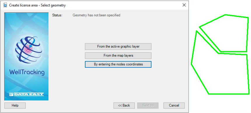
The Status line message will change to: Geometry has been specified.
Press Back to get back to the previous step of specifying the name of the license area, Next to get to the next step and Cancel to exit the Create license area dialog.
*****