


"Critical distance" tool
This tool is provided to find any intersection of wellbores of one well and to calculate critical distance between these wellbores.
-
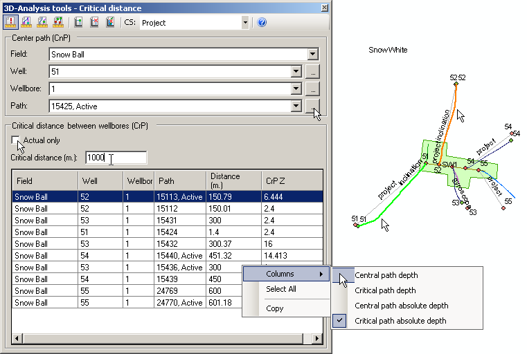
Select the required coordinate system from the list.
-
Specify the Central path (the path to be analyzed) parameters. All calculations will be performed based on this path parameters. The path can be selected from the list or on the map, by clicking on the required polyline. The selected path will be marked with green color. The Path text-box contains the OBJECTID of the path specified in the WELLBORE_GEOMETRY table and its status.
-
If you put the flag in the Actual only checkbox, the resulting table will contain only active wellbore geometries, located on the critical distance from the central wellbore path.
-
The critical distance is specified by the system administrator (Administration > Configuration parameters). By default the critical distance is set to 100 m. Though, this parameter can be changed manually in the Critical distance text-box.
The columns of the resulting table can be sorted by values.
If you select any row in the table, the correspondent path on the map will be marked with orange color.
Right-click on the selected row to call the contextual menu with the Columns, Select All and Copy options. .
-
The Columns option allows adding additional fields to the resulting table. These columns will contain values of the depth of the node along wellbore, absolute depths along central path and along paths located on critical distance from the central path. Check the required checkbox to see the appropriate field in the resulting table.
-
The Select All option is provided to select all rows in the resulting table. Appropriate objects will be marked with orange color on the map.
-
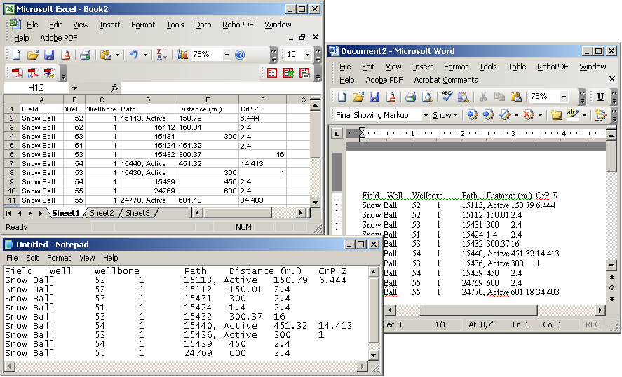
With the Copy option the values in the selected rows are copied to clipboard and can be further pasted to Notepad or MS Word and MS Excel applications.
*****